Body and Chassis
General
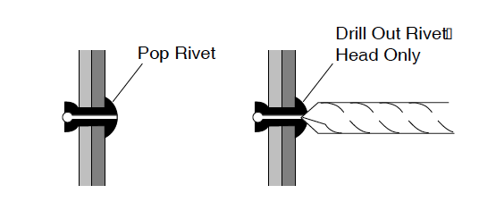
In general, body component replacement can be accomplished with a minimum of specialized tools. Most body components are held in place with conventional removable fastenings (nuts, bolts, washers and screws). Some components are mounted with ‘pop’ rivets which require that the rivet head be removed in order to push out the shank of the rivet.

The rivet head is easily removed by drilling into the head with a sharp drill bit that is slightly larger than the shank of the rivet. Care must be exercised when drilling to prevent the drill from being forced through the plastic body components where it could damage components located immediately behind the rivet. The best way to prevent this from occurring is to use a sharp drill bit that requires very little pressure to cut successfully and to place a piece of protective sheet metal between the surface being drilled and components directly behind it.
When installing a replacement instrument panel, a new console safety label MUST be ordered and placed on the new instrument panel. When ordering a replacement instrument panel, provide vehicle serial number to the Service Parts Representative who will provide the correct part number for the safety label.
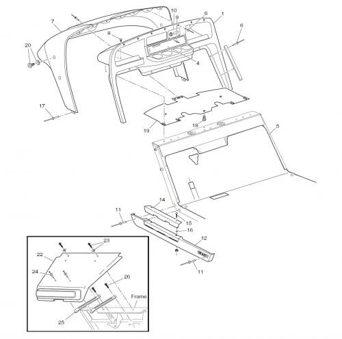
Using an insulated wrench, disconnect the battery cable at the negative (-) battery terminal. Pull the front of the floor mat up to expose the rivets that secure the instrument panel to the floor. Drill out the rivets attaching the bottom of the instrument panel to the floor and across the top of the instrument panel attaching it to the cowl. Remove the four screws located within the instrument panel pockets. The instrument panel may now be pulled away from the cowl.
Remove the drive rivets securing the ignition switch plate to the instrument panel. Rotate the ignition switch plate and push it through the instrument panel opening, freeing the panel for removal. Reassembly is the reverse order of disassembly and will require new rivets.
Cowl Replacement
Drill out the rivets across the top of instrument panel attaching it to the cowl. Remove the rivet at the front and back of each rocker panel.
Remove the rocker panel sill plates by removing the hardware securing them to the frame. As the sill plate is removed, be sure to catch the three spacers under each sill plate for reuse when sill plates are reinstalled. Drill out the rivets securing the sides of the cowl to the frame.
From underneath the cowl, remove the ratchet fastener attaching the center of the splash panel to the frame cross member. Remove the four screws located within the instrument panel pockets. Remove the bolts and washers from the sides of the cowl and lift the cowl assembly from the vehicle. Reassembly is the reverse order of disassembly and will require new rivets. The bolts and washers reinstalled into the cowl should be tightened to 8 – 12 ft. lbs.
Front Shield Replacement
The front shield need not to be removed to replace any other body components. If the front shield is damaged, remove hardware securing the front shield to the frame.
Remove the two rivets securing the front shield to the brackets. If a bracket is damaged, remove screw securing it to the frame after removing the front shield. Install replacement shield in reverse order of disassembly.
Rocker Panel Replacement
Remove the rocker panel sill plates by removing the hardware securing them to the frame. As the sill plate is removed, be sure to catch the three spacers under each sill plate for reuse when sill plates are reinstalled. To remove the rocker panel, remove the rivets at the front anad rear of the rocker panel . Unsnap the rocker panel from the vehicle frame. Replace rocker panel in reverse order of disassembly. Align the replacement sill plate with spacers in place and install hardware.
Body Replacement

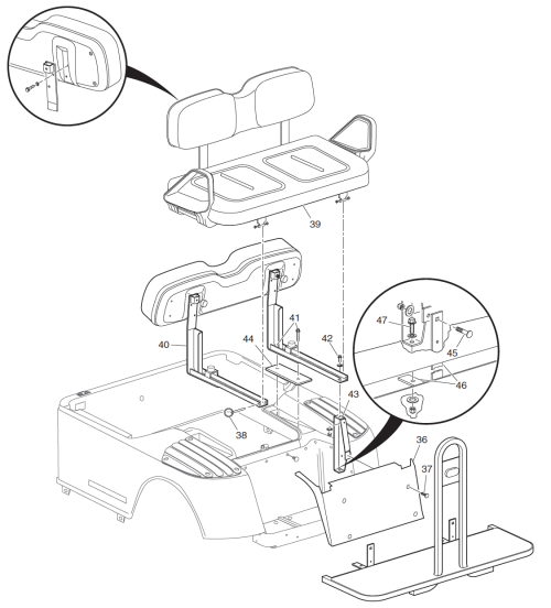
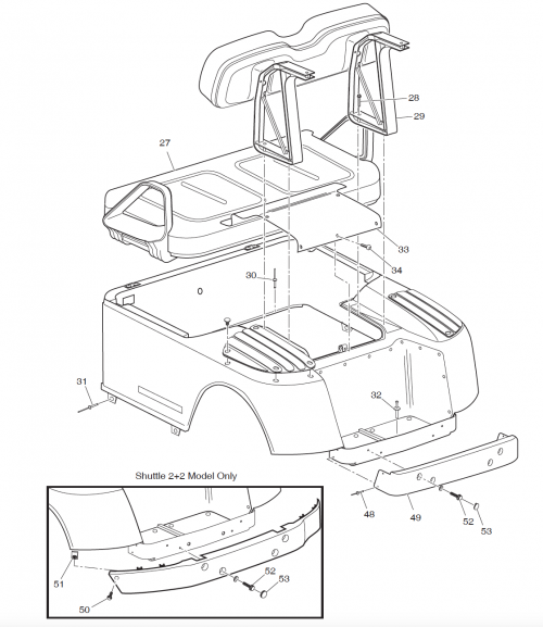
Remove hardware attaching seat back supports to body. At the front of the rear body, remove the rivets securing the rear body to the frame and floorboard area. Drill out the heads of the large head rivets that secure the bottom of the body panel to the side of the vehicle.
Remove the rivets that secure the floor of the bagwell area to the frame underneath. Remove the body. If the trunk lid is to be reused, remove the hardware securing the trunk lid to the body panel. Remove the trunk lid. Installation of rear body is in the reverse order of disassembly using new rivets. Install the bolts into the seat supports and tighten to 21 – 25 ft. lbs.
Shuttle 2+2 Component Replacement
Remove rear valance panel by prying out plastic fasteners. Remove the hardware attaching rear facing seat to the seat back supports. Remove the screws that secure seat back support to vehicle frame. Remove the hardware that secures seat back support to frame support. Remove each seat back support and spacer from the rear body. Repeat procedure on other seat back support.

Remove the hardware securing the vertical foot rest bracket to each frame support . Remove the nut securing the horizontal foot rest bracket to each frame support. While supporting the end of the foot rest, remove the bolt attaching the vertical bracket to the frame support. Replacement of the foot rest is the reverse order of removal. Tighten bolts to 21 – 25 ft. lbs. torque.
Rear Bumper Replacement

For Golf Cars, drill out rivets located at each end of the rear bumper. Carefully remove the plugs with a screwdriver. Remove the shoulder bolts underneath the plugs. Remove the rear bumper. To replace the bumper, place the rear bumper against the rear body panel and tighten the shoulder bolts to 9 – 12 ft. lbs. torque. Replace the plugs. Using the existing holes in the frame as a guide, drill holes in the bumper from underneath the vehicle and install new rivets. For Shuttle 2+2, remove bolt and J-nut located at each end of the rear bumper. Carefully remove the plugs with a screwdriver. Remove the shoulder bolts underneath the plugs. Remove the rear bumper. To install this type bumper, engage the top of the bumper with the underside of the fenders. Push bumper upward as fender slides between the bumper clips and the bumper. Insert bolts through holes in the bumper into the frame and tighten to 9 – 12 ft. lbs. torque. Tap a bumper cover plug into each hole. Secure each end of the bumper to the fender with bolt and J-nut.