Brake System
Brakes General
Your EZGO cart is fitted with a mechanically initiated rear drum brake system. The braking systems contains a service brake and park brake pedal, release linkage for park brake, compensator system, equalizer link, braking cables and wheel brake systems that self adjust.
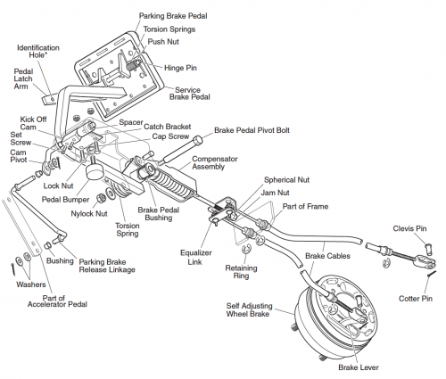
Brake Pedal and Linkage Inspection
1. Inspection of brake pedal return bumper.
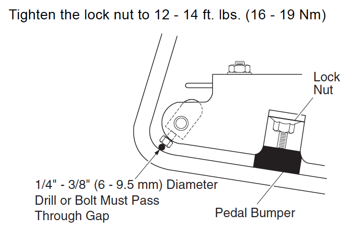
Ensure the brake pedal is meeting the pedal return bumper when disengaged. The bumper should be in good condition whereby a 1/4 – 3/8″ (6 – 9.5 mm) space occurs between the setscrew heads of the kick-off cam and brake pedal arm. If necessary replace the brake pedal system.
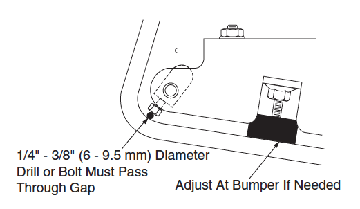
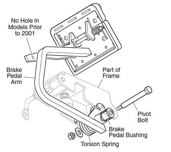
2. Inspection of brake pedal return.
Engage the brake and release. The brake pedal arm should contact the pedal bumper when disengaged. The torsion spring should be wrapped around the pedal and frame. Should the pedal have a slow return or not return home fully then the bushings and pivot bolt needs replacement. If necessary replace all pedal, spring, bushings and hold down bolt.
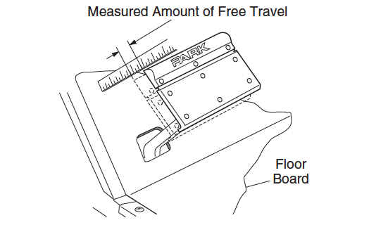
3. Inspection of the brake pedal for free travel.
Ensure the brake pedal has free travel at the point where the brake shoes first comes into contact with the brake drum. If too much free travel is experienced then you have a problem with either of your wheel brakes not self-adjusting or cables/linkages wear. Inappropriate pedal free travel means you have issues with either of wheel brake self-adjustment or brake linkages.
4. Inspection of the brake cables.
Look for damage or fraying of the inner cable and lack of fluid motion when pedal is engaged / disengaged. Ensure the cables are correct positioned within the cable supports. If any issues are experienced replace the cables and equalizers together.
5. Clevis Pins Inspection.
Inspect the clevis pins attached to the brake lever. The clevis pins must be slack when the brake is disengaged. IF the clevis pins are tight and everything else associated with the brake system is working correctly then the issue lies with the wheel brake.
6. Inspection of the brake cable equalizer linkage.
Carry out inspection looking for corrosion, damage, wear or severe misalignment Replace as necessary.
7. Inspection of the compensator assembly.
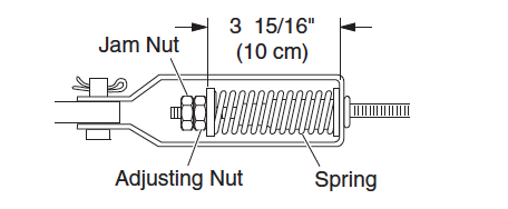
Carry out inspection for wear, corrosion and damage. Replace as necessary. Ensure park brake is off and then check compensator spring is 3 15/16” (10cm) long. If you need to lengthen or shorten the spring conduct this at the spring’s nuts at the front of the cart.
8. Inspection of parking brake pedal hinge.
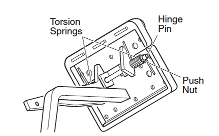
Carry out inspection for damaged or corroded springs and ensure the hinge pin retracts appropriately.
Engage park brake pedal to check smooth operation.
9. Condition and operation inspection of the parking
The park brake should automatically disengage when the accelerator pedal is energized.
10.Inspection of catch bracket and latch arm.
Inspect for wear, damage and corrosion and replace if found.
11. Inspect the parking brake kick-off cam.
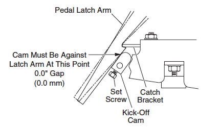
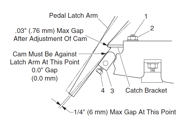
Carry out inspection for wear, damage and corrosion and ensure optimum adjustment. Engage the park brake and check that no gap exists between the cam top and latch arm. If necessary adjust the kick-off cam.
12.Inspection of kick-off cam linkage and bushings.
Carry out inspection for wear corrosion and damage. The pivot cam and bushings should be free to rotate and have no signs of rust. The kick-off cam should rotate when the accelerator pedal is pushed.
Wheel Brake Inspection
1. Brake drum cleaning.
Without affecting the adjuster mechanisms remove excess debris, dust and dirt from the drum with a brush.
2. Brake drum inspection.
Inspect the drum for bluish tinges or blistered paint then overheating has occurred,
Inspect the drum to see scoring whereby severe wear has left marks on the drum,
Inspect the splines for galling,
In the event of overheating, scoring or galling, change the brake drum.
3. Carry out inspection of axle seal and thrust washer for oil seepage.
4. Carry out inspection on condition and operation of adjuster mechanism. Carry out inspection of brake lever for damage and wear.
Carry out testing of adjuster accordingly to:
- Engage the front brake shoe towards the rear of the cart and hold,
- Engage the brake lever.
- The adjuster arm should engage the star wheel and start to rotate
Should the adjuster arm engage and rotate the star wheel then the system is working correctly.
Should the arm fail to engage the star wheel then it is not operating properly is damage and requires replacing. Replace both wheel brake assemblies.
Should the adjuster arm engage the star wheel however does not rotate it, then the adjuster assemblies require replacement.
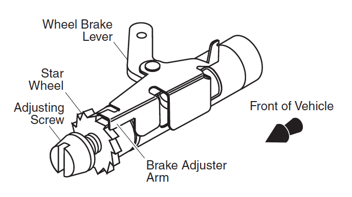
5. Condition and Operation checks of the moving anchor assembly. Engage the brake lever checking for fluid motions.
Should the moving anchor assembly bind or is damaged, replace both of the wheel brake assemblies.
6. Backing plate inspection.
Carry out inspection for gouges, galling or damage. More importantly is the contact point with the brake shoes. Replace as necessary.
7. Measurement of the brake shoe thickness.
Carry out measurement of the brake shoe exhibiting the most wear. The shoe thickness should be no less than .06″ (1.5 mm). Replace as necessary.
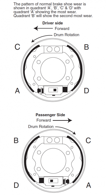
8. Inspection of the brake shoe springs.
Check for brakeage or damage and are fitted correctly. The hooked spring end is fitted to the front shoe, with the other end fitted to the adjuster. Brake shoe springs with the light spring near the adjusted mechanism, whereby the hook is fitted down inside the rear brake shoe and up inside the front brake shoe. The heavy top spring is fitted with all spring hooks fitted down inside the brake shoes.
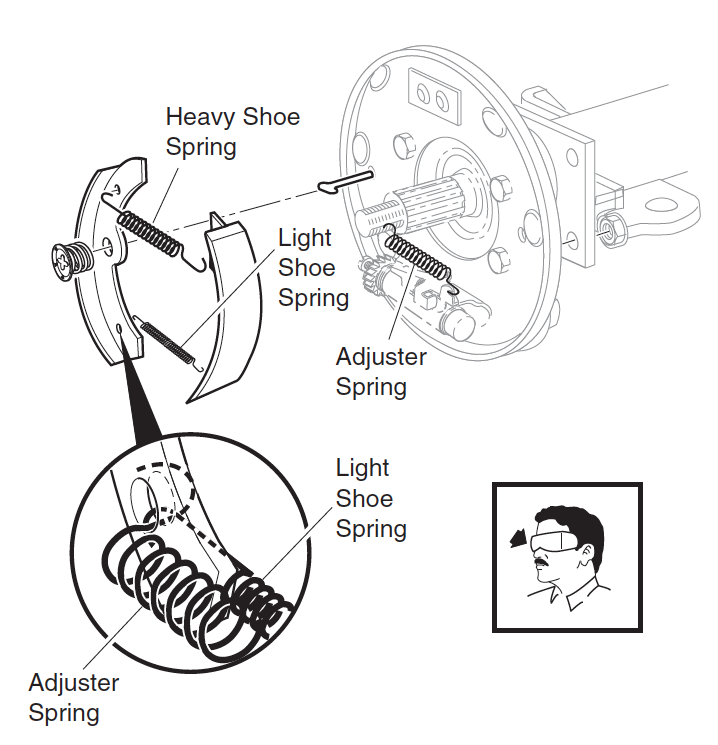
9. Same procedure for other wheel brake.
10.Inspect and adjust the brake pedals fluid travel.
MAINTENANCE AND REPAIRS
Adjust Brake Pedal Fluid Travel
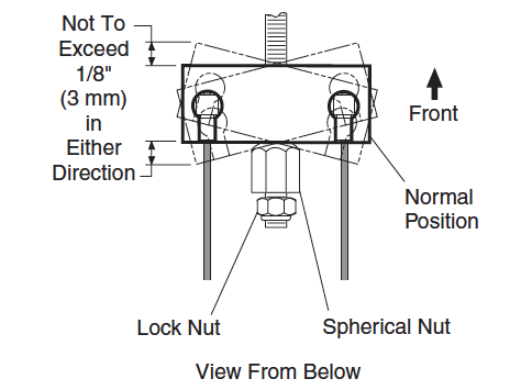
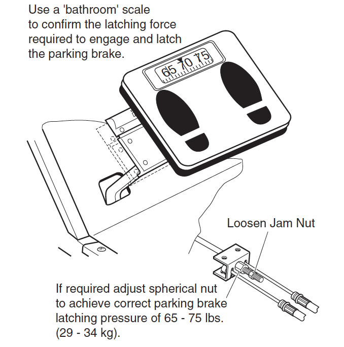
Brake pedal fluid travel is the gap the pedal moves from the stationary position to when the brake cables just begin to energize the brake levers. Adjusting the fluid travel is essential to ensure the brakes work correctly. If you experience too much pedal fluid travel you will have limited braking capacity. If you experience too little pedal fluid travel you will cause the brakes to not fully release.
Adjust the brake pedal fluid travel by loosing the nut and rotating the spherical nut. Torque the nut to 10-11ft. lbs. (14-15Nm). The optimum brake fluid travel setting should be 7/8″-1 1/8″ (2.2-2.9 cm).
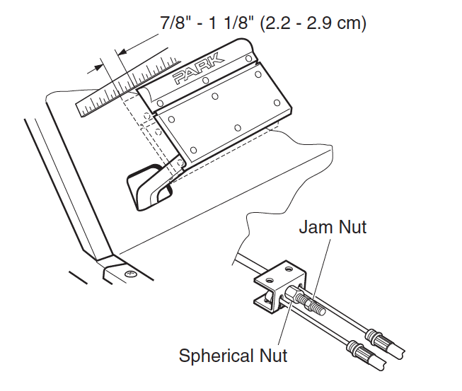
Energize the brake pedal quickly and hard 4 – 6 times to find the actual fluid travel.
Conduct a dynamic test by driving the cart slowly and energize the brakes quickly and hard. Allow the brakes to adjust freely and repeat test 10 times. When completed adjust the fluid travel with the spherical nut. Drive the cart again slowly and brake quickly and hard another 10 times. Check that the fluid free travel does not change during braking. If it does keep adjusting the spherical nut and conducting the test. Inspect the clevis pins at the end of the brake cables and brake levers are slack.
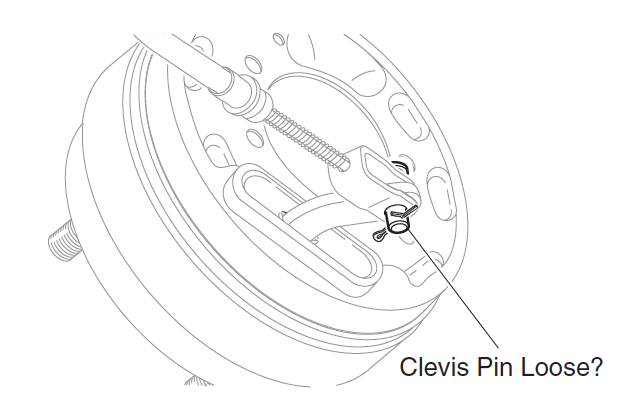
Correct as required.
Brake Drum Removal and Installation
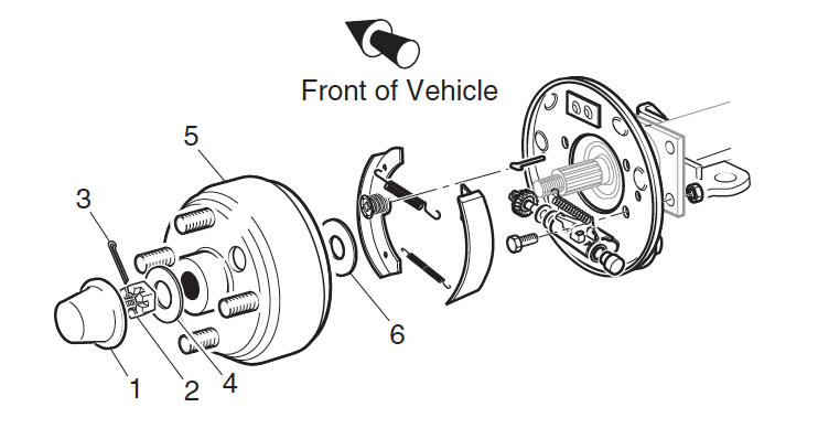
Remove
- Take off the dust cap,
- Access the castellated nut and cotter pin and remove,
- Remove washer and slide brake drum off the axle shaft,
- If the drum does not come off, the brake shoes need to slackened,
- Turn the hub such that the drum hole is at 6 o’clock, above the brake mechanism,
- Using a screwdriver lever the adjuster arm above the star wheel,
- Slacken the star wheel to pull back the brake shoes and allow the brake drum to come off freely.
Install
- Clean the axle shaft and splines removing dirt, grease and debris,
- Use WD-40 or equivalent to prevent seizing on the axle spline,
- Fit the inner brake drum washer and fit the brake drum in place,
- Check that brake drum nose is past the end of the axle splines. If not use another washer to space out the drum,
- Install castellated nut and cotter pin,
- Torque the nut to 80-90ft. lbs. (108-122Nm), do not exceed 140 ft. lbs. (190Nm).
Wheel Brake Service
To service the wheel brake you must disassembly, inspect, lubricate and reassembly the wheel brake assembly. Any damaged, worn or corroded items are to be replaced.
- Remove the brake drum as per “Brake Drum Removal and Installation“
- Clean off accumulated brake dust,
- Pull off brake shoes,
- Clean back plate and dry,
- Where the backing plate contacts with the brake shoes, lubricate,
- Refit the actuator assemblies, adjuster assemblies and brake shoes,
- Refit the springs,
- Refit brake drum,
- Adjust brake fluid travel.
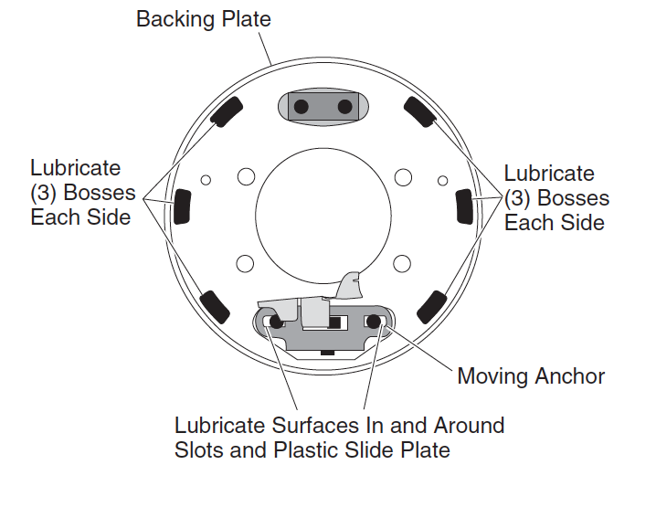
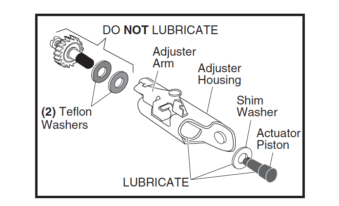
Backing Plate and Entire Wheel Brake Assembly
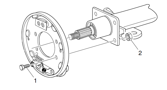
Removal and Installation
- Take off the four bolts and locking nuts that fits the wheel brake backing plate to axle tube flange,
- Take off the clevis pin that fits the brake cable to brake lever,
- For reinstatement follow reverse points above. Locknut torque is 23-28ft. lbs. (31-38Nm).
Brake Shoe and Adjuster Replacement
- Take off the three brake shoe springs and scrap,
- Retaining the shoe clamp pin in place, compress and turn the shoe clamp 90 degrees to remove it from the shoe clamp pin,
- Take off the brake shoes, adjusters and remaining components,
- Clean the backing plate and dry,
- When the backing plate contacts the brake shoes, lubricate,
- Refit the adjuster mechanism,
- Fit the adjusting screw into the star wheel nut only until 2 threads are exposed,
- Replacing both brake shoes assemblies on a common axle as a set and fit the shoe clamp into the shoe clamp pin, turning it 90 degrees to lock,
- Refit new brake shoe and adhuster springs. The hooked end of spring is fitted into the front shoe. The other end of the spring is fitted to the adjuster,
- Adjust brake fluid travel.
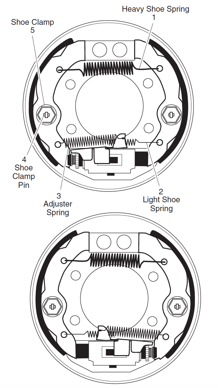
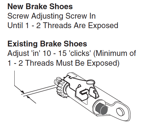
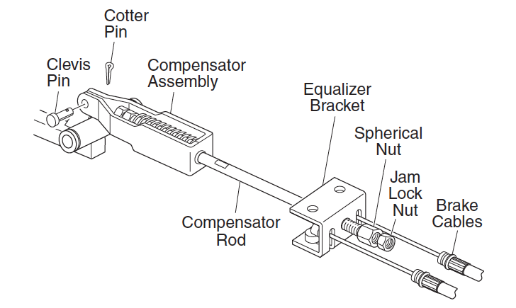
Compensator Assembly, Removal and Installation
- Remove the compensator assembly from the brake pedal by disconnecting the cotter pin and clevis pin,
- Slacken the nut and spherical nut that fist the compensator rod to the equalizer link,
- Take off compensator assembly,
- Installation is reverse of above,
- Adjust brake pedal fluid travel.
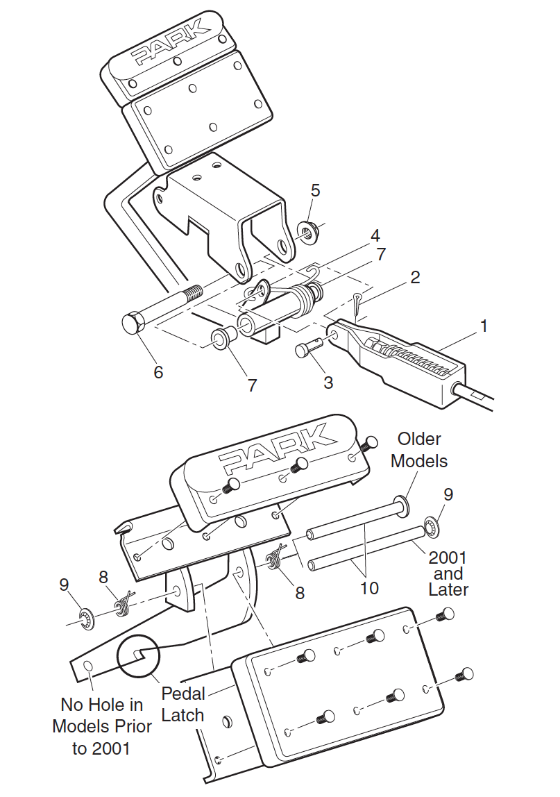
Brake Pedal Removal and Installation
- Remove the compensator assembly from the brake pedal by disconnecting the cotter pin and clevis pin,
- Disconnect the wiring harness where appropriate,
- Take off the torsion spring by levering off with a small screw driver between the hook and bracket,
- Take off the lock nut, shoulder bolt and disconnect the brake pedal,
- Check the shoulder bolt for corrosion, replace as necessary,
- Installation is reverse of above, Lock nut torque is 25-29ft. lbs. (34-39Nm).
Parking Brake Catch Bracket Removal and Installation
- Take off the driver side front wheel to have free access to the brake pedal release mechanism,
- Take off the two bolts and nuts fitted to the catch bracket
- Replace catch bracket,
- Refit nuts and bolts torqueing to 85-95 in. lbs. (10-11Nm).
Parking Brake Pedal, Removal and Installation
- Take off the push nut and pin and disconnect the parking brake pedal,
- To reinstate, fit the parking brake pedal and torque the push nut and pin.
Pedal Bumper Adjustment
- Slacken the bumper lock nut and manipulate the bumper by turning it,
- The brake pedal shall come into contact with the pedal bumper when then pedal is de-energized. The distance from the pedal arm to the setscrew heads in the kick-off cam is ¼”-3/8” (6-9mm). Torque the lock nut to 12-14 ft. lbs. (16-19 Nm).
Parking Brake Release Linkage Removal and Replacement
- Disconnect the cotter pin, washers and bushings off the linkage rod. Take off the linkage rod,
- Check the bushings and replace as necessary,
- Installation is in the reverse of above.
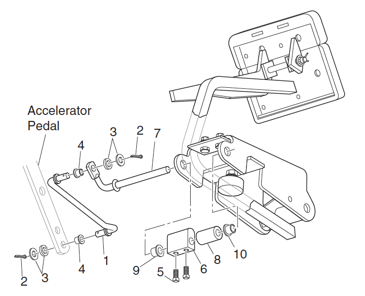
Parking Brake Kick-Off Cam Removal
Replacement and Installation
- Remove the parking brake release linkage,
- Slacken the two setscrews from the cam and take off the cam pivot, cam and spacer
- Check the bushings and spacer. Replace as necessary,
- Installation is in the reverse of above,
- Torque the setscrews to 45-55 in. lbs. (5-6 Nm) torque.